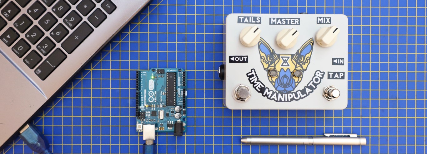
The Time Manipulator is a programmable Arduino based Delay/Echo/Reverb guitar pedal. It uses two PT2399 delay integrated circuits to archive up to 600ms delay. Also, with the help of 4 analog switches, the internal configuration of the pedal can change: placing the PT2399 delay chips in series or parallel and adding extra features:
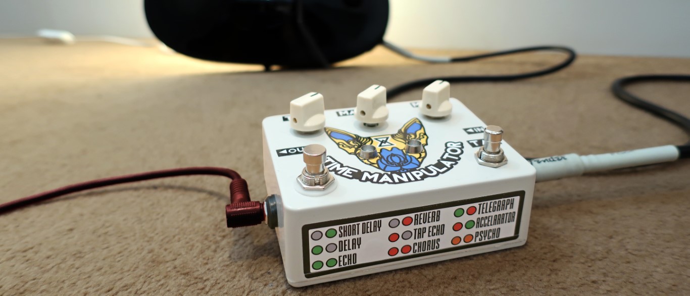
The code for the Arduino chip is programmed in C and it is Open-Source, so users can re-program the functionality or add new effects and share them in the forum. There are 9 effects included by default in the pedal: short delay, delay, echo, reverb, tap echo, chorus, telegraph, accelerator, and psycho. The schematic and bill of materials are public, the circuit was designed using easy-to-find and through-hole components.

Time Manipulator Specifications:
- True Bypass.
- Based on Arduino UNO ATMEGA328P-PU (8MHz, 1KB RAM) microcontroller.
- Analog input/output stages using MCP6002 operational amplifiers.
- Interface:
- 1 Mix knob (blends dry and wet signal)
- 1 Tails Knob (adjust the number of echo repetitions)
- 1 Tap foot-switch (programmable)
- 1 3PDT True Bypass foot-switch
- 1 Encoder knob + Push Button
- 2 x Dual color LEDs (programmable).
- Connectors:
- Input Guitar Jack, 1/4 inch unbalanced mono, Zin=1MΩ.
- Output Guitar Jack, 1/4 inch unbalanced mono, Zout=0.1Ω.
- Power supply: standard 9V Boss connector (center tip positive)
Documentation Available:
- Time Manipulator Assembly Guide (pdf)
- How to Start Programming the Time Manipulator.
- Bill of Materials (BOM) (pdf)
- PCB Plan (pdf)
- 1590BBS Drilling Stencil (pdf)
- Schematic (pdf)
- Time Manipulator Instructions (pdf)
- Forum
Time Manipulator Review by BlitzCityDIY:
Have a look to the deep Blitz City DIY review on the pedal:
The Time Manipulator Schematic:
The circuit can be broken down into 6 simple blocks: Power Supply, Input Buffer, Dual PT2399 Delay Stage, Output Adder, Analogue Switches, and the Arduino Block:

The main tasks of the circuit parts are:
- Power Supply: generates energy (+9V and +5V) and bias voltage (+4.5V) for all the circuit.
- The Input Buffer is an op-amp with gain=1. It will present a high input impedance (Zin=1MΩ) and prepare the signal for the rest of the circuit.
- Dual PT2399 Delay Stage: The two PT2399 in the classic Delay configuration can create a delay from 30 to 600ms approx.
- Arduino Controlled Current Sink: The Arduino microcontroller controls the amount of delay with a PWM signal. The op-amp current sink is used to transform the PWM into current thus delay that the PT2399 will have.
- The Output Adder: it will give a low output impedance to preserve the sound quality on the pedal chain. Its main task is to blend the original guitar signal together with the different delay paths or "taps".
If you want to understand all the circuit details and values, please check the Time Manipulator Circuit Analysis in the forum.

A Morphing Circuit:
The Time manipulator uses 4 analog switches (CD4066). They will allow the signal to follow different paths and create different sounds. You will have the possibility to place the PT2399 in series (extending the time and definition of the delay time) or in parallel (creating different sounds like reverb or chorus/delay).
The principal configurations are:

Briefly going over the most important configurations, we have:
- Short Delay: The first PT2399 is not used, this mode archive delays from 30ms to 300ms approx. Simple and clean.
- Delay: This is the basic configuration, the 2 PT2399s are used in series, getting delays from 60ms to 600ms approx. The Tails pot will add more depth to this mode.
- Echo Mode1 and 2: The basic Delay mode could be enriched, adding extra tap paths for the signal.
- Super Echo: All the relays are on, giving a no-stopping bouncing sound.
- Parallel - Chorus: The two delay units are placed in parallel, using subtle different delay times on each one will give a chorus-like sound.
- Reverb: The idea is to add to the original guitar signal two paralleled delayed copies (mimicking the signal bouncing over 2 walls). The delays need to be short here to have a realistic effect.
- Telegraph: All the relays are OFF and we the foot tap we can control the dry signal going through the pedal.
Programming the Time Manipulator:
To make the programming as easy as possible, we use the standard Arduino IDE. All the effects are programmed on C using the standard Arduino functions. All tools and programs are free-of-charge/Open Source.
Basic knowledge of C is needed to understand the codes. We have created some content to help you to understand how to program and create codes:
- How to Start Programming the Time Manipulator.
- Programming My First Time Manipulator Effect.
- How to Reprogram the Time Manipulator.
- Delay Effect Code.
The best way to illustrate how to program it's by showing a simple Echo Effect example:

The real code looks like this:
// Pin Definitions:
#define DELAY1 10
#define DELAY2 9
#define SWA 3
#define SWB 14
#define SWC 2
#define SWD 4
#define LED1_G 1
#define LED1_R 0
#define LED2_G 5
#define LED2_R 6
#define ENC_A 16
#define ENC_B 18
#define ENC_GND 17
#define ENC_PUSH 19
#define BYPASS_DETECT 8
#define TAP_DETECT  15

//VARIABLES
unsigned int ENC_counter = 100;
int ENC_aState;
int ENC_aLastState;
int ENC_aState_selection=0;
int ENC_aLastState_selection=0;
void read_encoder(void);

// the setup function runs once when you press reset or power the board
void setup()
{
//set the pins //init the values
pinMode(DELAY1, OUTPUT);    analogWrite(DELAY1, 100);
pinMode(DELAY2, OUTPUT);    analogWrite(DELAY2, 100);
pinMode(SWA, OUTPUT);       digitalWrite(SWA, LOW);
pinMode(SWB, OUTPUT);       digitalWrite(SWB, LOW);
pinMode(SWC, OUTPUT);       digitalWrite(SWC, LOW);
pinMode(SWD, OUTPUT);       digitalWrite(SWD, LOW);
pinMode(LED1_G, OUTPUT);    analogWrite(LED1_G, 0);
pinMode(LED1_R, OUTPUT);    analogWrite(LED1_R, 0);
pinMode(LED2_G, OUTPUT);    analogWrite(LED2_G, 0);
pinMode(LED2_R, OUTPUT);    analogWrite(LED2_R, 0);
pinMode(ENC_A, INPUT_PULLUP);
pinMode(ENC_B, INPUT_PULLUP);
pinMode(ENC_GND, OUTPUT);
pinMode(ENC_PUSH, INPUT_PULLUP);
pinMode(BYPASS_DETECT, INPUT_PULLUP);
pinMode(TAP_DETECT, INPUT_PULLUP);
ENC_aLastState = digitalRead(ENC_A);
}


void loop() // the loop function runs over and over again forever
{
//detect if the effect is on or off
while((digitalRead(BYPASS_DETECT) == LOW))
  {
  digitalWrite(LED1_R,LOW);digitalWrite(LED2_R,LOW);digitalWrite(LED1_G,LOW);digitalWrite(LED2_G,LOW);
  }

read_encoder();
//update the delay value based on the encoder reading
analogWrite(DELAY1, ENC_counter);
analogWrite(DELAY2, ENC_counter);
//update the LED colors
digitalWrite(LED1_G, HIGH); digitalWrite(LED2_G, HIGH);digitalWrite(LED1_R,LOW);  digitalWrite(LED2_R,LOW);
//set the audio relay
digitalWrite(SWA, HIGH);digitalWrite(SWB, HIGH);digitalWrite(SWC, HIGH);digitalWrite(SWD, HIGH);
}

void read_encoder(void)
{
 ENC_aState = digitalRead(ENC_A); // Reads the "current" state
   if (ENC_aState != ENC_aLastState)
   {
     if (digitalRead(ENC_B) != ENC_aState)
          {if(ENC_counter>50)ENC_counter-=5;}
     else
          {if(ENC_counter<230)ENC_counter+=5;}
   }
ENC_aLastState = ENC_aState; // Updates the prev. state
}
Short Description of the code:
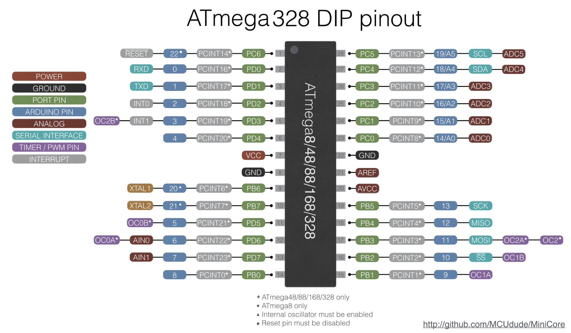
- Lines 1 to 17: Define the pin names, so it is easier to refer to the pins during the code. Have a look at the ATMEGA328P-PU pinout if you have any question.
- Lines 19 to 25: Define variables used in the program, in this case, all of them are used for reading encoder
- Setup (lines 28 to 48): set the microcontroller pins as inputs or outputs and assign a default value (high or low)
- Loop (lines 51 to 80): The main loop is executed running, again and again, it has 5 main tasks:
- Check the True Bypass Footswitch and activate or deactivate the effect.
- Read the encoder: the read_encoder function is explained on the Arduino website.
- Update the amount of delay depending on the encoder value using analogWrite. The recommended values are between 50 (min delay) delay and 230 (max delay).
- Update the LED colors (both green in this example) and the audio relays configuration (all are ON in this example)
Buy Time Manipulator Online:
There are 2 options in the shop:
- Order only the PCB. It uses easy to find through-hole components and you can build the kit yourself using the public Bill of Materials.
- Order the Full Kit: This kit includes the PCB, Cover and all the components to build the Time Manipulator at home.
Time Manipulator Components List:
If you have any question, contact us.
| Time Manipulator - Bill of Materials | ||||
| Reference | Description | Manufacturer/Mouser PN | Manufacturer | |
| Units | Resistors | |||
| 1 | R2 | 5KΩ Res 1%, 1/4W | MFR-25FRF52-4K99 | Yaego |
| 1 | R1 | 1MΩ Res 1%, 1/4W | MFR-25FRF52-1M | Yaego |
| 26 | R3, R4, R5, R6, R7, R8, R9, R10, R11, R12, R13, R14, R15, R16, R17, R18, R19, R20, R21, R22, R23, R25, R28, R29, R30, R31 |
4.7KΩ Res 1%, 1/4W | MFR-25FRF52-4K7 | Yaego |
| 2 | R26, R27 | 470Ω Res 1%, 1/4W | MFR-25FRF52-470R | Yaego |
| 2 | RV1, RV2 | 10K linear pot 16mm | RV16AF-41-15R1-B10K-3 | Yaego |
| Capacitors | ||||
| 18 | C2, C3, C4, C5, C6, C8, C9, C12, C17, C21, C22, C24, C27, C36, C37, C38, C39, C41 |
47uF | REA470M1CBK-0511P | Lelon |
| 4 | C7, C15, C23, C29 | 6.8nF | SR211C682MARTR1 | AVX |
| 15 | C1, C10, C13, C16, C18, C19, C20, C25, C30, C31, C32, C33, C34, C35, C40 |
100nF | SR211C104KARTR1 | AVX |
| 4 | C11, C14, C26, C28 | 3.3nF | SR215C332MARTR1 | AVX |
| Diodes | ||||
| 1 | D1 | 1N5817 | 511-1N5817 | STMicroE |
| 2 | D2, D3 | TLUV5300 | TLUV5300 | Vishay |
| Semiconductors | ||||
| 2 | Q1, Q2 | 2n5089 | 610-2N5089 | Central |
| 1 | U1 | TL072 (or MCP6002) | TL072 | Ti |
| 1 | U5 | MCP6002 | MCP6002 | Microchip |
| 2 | U3, U6 | PT2399 | eBay-Amazon-Tayda-etc | Princetown |
| 1 | U2 | LM7805 | 926-LM7805CT/NOPB | Ti |
| 1 | U4 | CD4066 | 595-CD4066BE | Ti |
| 1 | U7 | ATMEGA328P-PU | 556-ATMEGA328P-PU | Atmel |
| Dip Sockets x 6 | ||||
| Other | ||||
| 1 | ENC1 (Encoder) | Encoder with Switch | RE111F-41B3-25F-15P (Rapid) | Alpha |
| 2 | J2, J7 | 1/4 Stereo Jack | NMJ6HCD2 | Neutrik |
| X | J2, J4, J5, J6, J7, J9, J10, J8, J40 | DNF Connectors | 22AWG solid wire | |
| 1 | J12 | SPDT Toggle Switch | SF12011F-0202-20R-M-027 (Rapid) | Alpha |
| 1 | SW5 | 3PDT Footswitch | 107-SF17020F-32-21RL | Alpha |
| 1 | J1 | 2.1mm power Jack | 163-4302-E | Various |
| 1 | Enclosure | Hammond 1590BBSLG | Any color from 1590BBS series | Hammond |
| 1 | Board to board connector | FSN-21A-10 | 22AWG solid wire also possible | TE |
| 1 | Interconnection wire 25cm | 22 AWG solid core wire | Various | |
| 3 | Knobs | Davies 1510 model | 1510AH | Davies |
| 2 | Led Holders | 5mm LED Metal Holders | 485-2176 | Adafruit |
| 1 | Time Manipulator PCB | Printed Circuit Board | Time Manipulator | ElectroSmash |
| 1 | Sticker | Labels | Time Manipulator Sticker | ElectroSmash |
Thanks for reading, all feedback is appreciated: This email address is being protected from spambots. You need JavaScript enabled to view it.
Some Rights Reserved, you are free to copy, share, remix and use all material.
Trademarks, brand names and logos are the property of their respective owners.


