Pedal-Pi is a lo-fi programmable guitar pedal that works with the Raspberry Pi ZERO Board. The project is totally Open Source & Open Hardware and made for hackers, programmers, and musicians that want to experiment with sounds and learn about digital audio.
You can code your own effects using standard C and get inspiration from the ready-to-use effects from the forum, like the Clean/Transparent, Booster/Volume, Distortion, Fuzz, Delay, Echo, Octaver, Reverb, Tremolo, Looper, etc.
The project was created with the aim of having fun and learning about guitar pedals. If you want to program digital audio effects in C without deep knowledge of DSP languages or electronics, this pedal is for you. But take also into consideration that it is only 12 bits and does not feel like a finished pedal that you could buy in a shop.

Specifications.
- Based in Raspberry Pi Zero (1GHz ARM11 core).
- Analog stages using MCP6002 rail-to-rail operational amplifier.
- ADC: 12bits / Sampling Rate 50Ksps (MCP3202).
- Output Stage: 12 bits (2x6bits PWMs running in parallel)
- Pi Zero:
- 1GHz ARM11 core.
- 512MB of LPDDR2 SDRAM.
- Micro-SD card slot.
- Interface:
- 2 Configurable push buttons.
- 1 Configurable switch.
- 1 programmable blue led.
- True Bypass Foot-switch.
- Connectors:
- Input Jack, 1/4 inch unbalanced, Zin=0.5MΩ.
- Output Jack, 1/4 inch unbalanced, Zout=100Ω.
- Power supply: power taken from the Pi Zero board (micro-USB).
Review by Blitz City DIY:
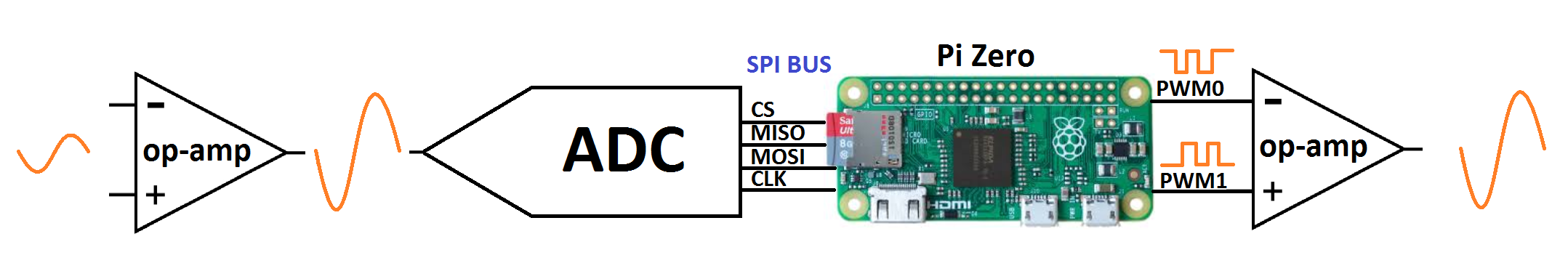
How Does the Circuit Work?
This hat has three parts:
- The Input Stage: Amplifies and filters the guitar signal making it ready for the ADC (Analog to Digital Converter). The ADC sends the signal to the PI ZERO using SPI communication. In the forum, the topic "Using MCP3202 ADC with Raspberry Pi Zero" gives more details about the ADC-Pi ZERO connection.
- Pi ZERO: It takes the digitalized audio waveform from the ADC and does all the Digital Signal Processing (DSP) creating effects (distortion, fuzz, delay, echo, tremolo...). In the forum, the topic "Basics of Audio DSP in C for Raspberry Pi Zero" can assist you to learn the basics.
- The Output Stage: Once the new digital waveform is created, the Pi Zero creates an analog signal with two PWMs combined, the signal is filtered and prepared to be sent to the next pedal or the guitar amp. For more info check the topic "PWM Audio on Raspberry Pi Zero".

If you want to understand all the details of the circuit, please read the Pedal-Pi Circuit Analysis:
How to Program it?
The idea is to make it as easy as possible, the examples are programmed in C using the standard BCM2835 Libraries. The Operating System used is Raspbian. All tools and programs are free/open source. In the forum, there is a topic called "How to Start Programming Pedal-Pi" with more details.
Basic knowledge of Arduino, Linux and C are needed. Have a look at the real code of a Clean effect:
Clean Effect Pedal:
The block diagram of this code looks like this:

The real code used looks like this:
// CC-by-www.Electrosmash.com Pedl-Pi open-source project
// clean.c effect pedal, the signal is read by the ADC and written again using 2 PWM signals.

#include <stdio.h>
#include <bcm2835.h>

// Define Input Pins
#define PUSH1             RPI_GPIO_P1_08      //GPIO14
#define PUSH2             RPI_V2_GPIO_P1_38   //GPIO20
#define TOGGLE_SWITCH     RPI_V2_GPIO_P1_32   //GPIO12
#define FOOT_SWITCH       RPI_GPIO_P1_10      //GPIO15
#define LED               RPI_V2_GPIO_P1_36   //GPIO16

uint32_t read_timer=0;
uint32_t input_signal=0;

uint8_t FOOT_SWITCH_val;
uint8_t TOGGLE_SWITCH_val;
uint8_t PUSH1_val;
uint8_t PUSH2_val;


//main program
int main(int argc, char **argv)
{
    // Start the BCM2835 Library to access GPIO.
    if (!bcm2835_init())
    {printf("bcm2835_init failed. Are you running as root??\n"); return 1;}


    // Start the SPI BUS.
    if (!bcm2835_spi_begin())
    {printf("bcm2835_spi_begin failed. Are you running as root??\n"); return 1;}

    //define PWM mode
    bcm2835_gpio_fsel(18,BCM2835_GPIO_FSEL_ALT5 ); //PWM0 signal on GPIO18
    bcm2835_gpio_fsel(13,BCM2835_GPIO_FSEL_ALT0 ); //PWM1 signal on GPIO13
    bcm2835_pwm_set_clock(2);                      // Max clk frequency (19.2MHz/2 = 9.6MHz)
    bcm2835_pwm_set_mode(0,1 , 1);                 //channel 0, markspace mode, PWM enabled.
    bcm2835_pwm_set_range(0,64);                   //channel 0, 64 is max range (6bits): 9.6MHz/64=150KHz PWM freq.
    bcm2835_pwm_set_mode(1, 1, 1);                 //channel 1, markspace mode, PWM enabled.
    bcm2835_pwm_set_range(1,64);                   //channel 0, 64 is max range (6bits): 9.6MHz/64=150KHz PWM freq.

    //define SPI bus configuration
    bcm2835_spi_setBitOrder(BCM2835_SPI_BIT_ORDER_MSBFIRST);      // The default
    bcm2835_spi_setDataMode(BCM2835_SPI_MODE0);                   // The default
    bcm2835_spi_setClockDivider(BCM2835_SPI_CLOCK_DIVIDER_64);    // 4MHz clock with _64
    bcm2835_spi_chipSelect(BCM2835_SPI_CS0);                      // The default
    bcm2835_spi_setChipSelectPolarity(BCM2835_SPI_CS0, LOW);      // the default

    uint8_t mosi[10] = { 0x01, 0x00, 0x00 }; //12 bit ADC read channel 0.
    uint8_t miso[10] = { 0 };

    //Define GPIO pins configuration
    bcm2835_gpio_fsel(PUSH1, BCM2835_GPIO_FSEL_INPT);           //PUSH1 button as input
    bcm2835_gpio_fsel(PUSH2, BCM2835_GPIO_FSEL_INPT);           //PUSH2 button as input
    bcm2835_gpio_fsel(TOGGLE_SWITCH, BCM2835_GPIO_FSEL_INPT);   //TOGGLE_SWITCH as input
    bcm2835_gpio_fsel(FOOT_SWITCH, BCM2835_GPIO_FSEL_INPT);     //FOOT_SWITCH as input
    bcm2835_gpio_fsel(LED, BCM2835_GPIO_FSEL_OUTP);             //LED as output

    bcm2835_gpio_set_pud(PUSH1, BCM2835_GPIO_PUD_UP);           //PUSH1 pull-up enabled
    bcm2835_gpio_set_pud(PUSH2, BCM2835_GPIO_PUD_UP);           //PUSH2 pull-up enabled
    bcm2835_gpio_set_pud(TOGGLE_SWITCH, BCM2835_GPIO_PUD_UP);   //TOGGLE_SWITCH pull-up enabled
    bcm2835_gpio_set_pud(FOOT_SWITCH, BCM2835_GPIO_PUD_UP);     //FOOT_SWITCH pull-up enabled

    while(1) //Main Loop
    {
    //Read the PUSH buttons every 50000 times (0.25s) to save resources.
    read_timer++;
    if (read_timer==50000)
    {
    read_timer=0;
    uint8_t PUSH1_val = bcm2835_gpio_lev(PUSH1);
    uint8_t PUSH2_val = bcm2835_gpio_lev(PUSH2);
    TOGGLE_SWITCH_val = bcm2835_gpio_lev(TOGGLE_SWITCH);
    uint8_t FOOT_SWITCH_val = bcm2835_gpio_lev(FOOT_SWITCH);
    bcm2835_gpio_write(LED,!FOOT_SWITCH_val); //light the effect when the footswitch is activated.
    }

    //read 12 bits ADC
    bcm2835_spi_transfernb(mosi, miso, 3);
    input_signal = miso[2] + ((miso[1] & 0x0F) << 8);

    //**** CLEAN EFFECT ***///
    //Nothing to do, the input_signal goes directly to the PWM output.

    //generate output PWM signal 6 bits
    bcm2835_pwm_set_data(1,input_signal & 0x3F);
    bcm2835_pwm_set_data(0,input_signal >> 6);
    }

    //close all and exit
    bcm2835_spi_end();
    bcm2835_close();
    return 0;
}
This is a graphical representation of the whole process:
Online Learning Material
We have prepared a series of articles for you to learn more about Digital Signal Processing for Audio, Raspberry Pi PWM Audio, ADC connection, and guitar effects.
- Basics of Audio DSP in C for Raspberry Pi Zero
- PWM Audio on Raspberry Pi Zero
- Using MCP3202 ADC with Raspberry Pi Zero.
- Pedal Pi Circuit Analysis.
- How to Start Programming Pedal-Pi
- Pedal-Pi Best Forum Topics
You can find more info in the Pedal-Pi Forum.
There are 2 options in the online shop:
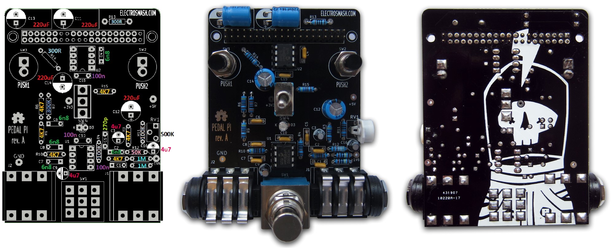
- Order only the PCB. It uses easy-to-find standard components and you can build the kit yourself. The bill of materials is public with all the references and the Mouser part numbers.
- Order the Full Kit: This kit includes the PCB, Cover and all the components to build Pedal-Pi at home. You would only need to buy the raspberry Pi-Zero by yourself.
If you have any question, contact us.

The components are easy-to-find through-hole parts with the minimum number of references:
| Pedal-Pi Bill of Materials. | ||||
| Reference | Qty | Value | Description | Mouser Reference |
| Capacitors | ||||
| C2,C4, C6, C7, C8 | 5 | 6.8nF | ceramic cap | SR211C682MARTR1 |
| C1, C10, C15 | 3 | 100nF | ceramic cap | SR211C104KARTR1 |
| C3, C9, C16 |
3 | 4.7uF | electrolytic cap | ECE-A1EKA4R7 |
| C5 | 1 | 270pF | ceramic cap | K271J15C0GF5TL2 |
| C11, C12, C13, C14 | 4 | 220uF | electrolytic cap | REA221M1CBK-0811P |
| Resistors | ||||
| R0, R1 |
2 | 1MΩ | Resistor, 1%,1/4W | MFR-25FRF52-1M |
| R2, R3, R6, R9, R10, R15 |
6 | 4.7KΩ | Resistor, 1%,1/4W | MFR-25FRF52-4K7 |
| R4, R11 |
2 | 100KΩ | Resistor, 1%,1/4W | MFR-25FRF52-100K |
| R7 | 1 | 300KΩ |
Resistor, 1%,1/4W | MFR-25FRF52-300K |
| R12 | 1 | 50KΩ | Resistor, 1%,1/4W | MFR-25FRF52-49K9 |
| R13, R14 | 2 | 300Ω | Resistor, 1%,1/4W | MFR-25FRF52-300R |
| Others | ||||
| RV1 | 1 | 500K | resistor trimmer | 3319W-1-504 |
| D3 | 1 | Led 3mm blue | blue led 3mm | SSL-LX3044USBC |
| U1 | 1 | MCP6002 |
op-amp rail-to-rail, pdip8 |
MCP6002 |
| U2 | 1 | MCP3202 | 12bit ADC, p-dip8 | MCP3202 |
| IC Socket | 2 | dip 8 socket | socket dor dip8 | 1-2199298-2 |
| SW1 | 1 | 3DPT footswitch | 3PDT footswitch | 107-SF17020F-32-21RL |
| SW4 | 1 | Toggle switch | SPDT toggle switch | 612-100-A1111 |
| SW2, SW3 | 2 | Pushbutton | off-on pushbutton | |
| Conn1 | 1 | 40 pin header |
2.54 pitch pin header | |
| J1, J2 | 2 | 1/4 Jack audio | stereo 6.35mm jack | NMJ6HCD2 |
| PCB + Cover + Screws |
||||
| Pedal Pi PCB | 1 | electrosmash store | ||
| Acrylic Cover | 1 | electrosmash store | ||
| M2.5x25 + 6 nuts | 8 | |||
Frequently Asked Questions (FAQ):
Where can I buy the Raspberry Pi ZERO board?
- In the official Raspberry Pi Zero website there is a list of shops and distributors where you can buy it. You can also find it on eBay or Amazon.
Is Pedal-Pi compatible with all Raspberry Pi boards?
- Not yet, we developed this project for PI ZERO but in theory, it would be compatible with other Raspberry Pi boards.
Is Pedal-Pi suitable for bass players?
- Yes, but you need to swap 1 capacitor (C1) from 0.1uF to 0.47uF, allowing lower frequencies into the circuit, that is all. If you are buying the kit in our store, send us an email and we will include this cap for you.
Can I plug headphones directly to pedal Pi?
- No, pedal Pi is not an amplifier. It needs to be plugged to a guitar amplifier, or to a multi-effects (Line 6 pods, etc..).
Thanks for reading, all feedback is appreciated 
Some Rights Reserved, you are free to copy, share, remix and use all material.
Trademarks, brand names and logos are the property of their respective owners.


