- Posts: 4
- Thank you received: 0
How to Troubleshoot pedalSHIELD MEGA
4 years 8 months ago - 4 years 8 months ago #1925
by Tigibus
Replied by Tigibus on topic How to Troubleshoot pedalSHIELD MEGA
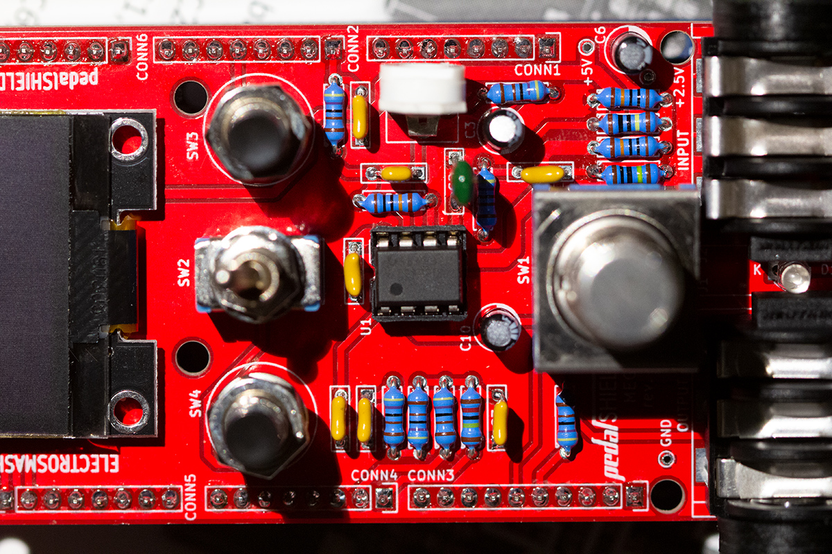
Here is an image of my board(I just change C2 6.8nF cap for a better one recently, I suspected it was the problem but nothing changes).
EDIT : Are you sure of your TL972 ??? Do you test them ?
EDIT : Are you sure of your TL972 ??? Do you test them ?
Last edit: 4 years 8 months ago by Tigibus.
Please Log in to join the conversation.
4 years 7 months ago #1926
by Ray
Replied by Ray on topic How to Troubleshoot pedalSHIELD MEGA
Hi:
If you have a big drop after R2 is because too much current is passing through that R2 resistor.
Could you unplug the op-amp and measure again? just to check if its the op-amp the one which is taking that extra current or maybe your pedal is oscillating.
I do not check the chips, I get them from one of the the best suppliers in the US (Mouser) and send them out directly.
Thanks. But all the Voltages mentioned before does not fit with yours. After R2 I found 1.40V like on PIN 5 but 2.4V at 2.5V area before R2.
I used a lot of time the image from your link to double check all the tracks on the PCB and where are supposed to be the different components and it's exactly like mine. I can make a Copy/Paste for your photo and my board.
If you have a big drop after R2 is because too much current is passing through that R2 resistor.
Could you unplug the op-amp and measure again? just to check if its the op-amp the one which is taking that extra current or maybe your pedal is oscillating.
I cannot read the TL972 legend on your image but I guess that it's difficult to read with the camera.EDIT : Are you sure of your TL972 ??? Do you test them ?
I do not check the chips, I get them from one of the the best suppliers in the US (Mouser) and send them out directly.
Please Log in to join the conversation.
4 years 7 months ago #1928
by Ray
Replied by Ray on topic How to Troubleshoot pedalSHIELD MEGA
hi, thats very weird, look my image below:

- If you remove the op-amp, not current will be flowing into the pin 5 (i2=0)
- Also, C1 will not allow any DC current to flow through it (i1=0)
So if you have 1.21V on R2, where is that current going to?
Are you sure that you have 2.5V at the voltage divider (make sure that this 2.5V are stable, not jumping).
If you are powering the circuit using USB its normal not to have 5V (you will probably have 4.7 or 4.8V) so the divider will be 2.4 or so.
Could you try to pore the Arduino using a standard 12V supply? maybe the 5V regulator on the Arduino board is not working properly.
Please Log in to join the conversation.
4 years 7 months ago #1930
by eshoji
Replied by eshoji on topic How to Troubleshoot pedalSHIELD MEGA
Hi,
I have received my pedalShield MEGA from you yesterday in Japan. Thank you very much for your attractive great products!
I am using 9V DC supply. First I experienced the same issue of 1.2V on R2. So, I switched to use volt meter that has higher input impedance (FET electronic tester). I have 2.4V at pin5 now (no TL972 seated on the socket). The question, where is that current going to? There will be current flows across the internal resistance of the volt meter that doesn't have higher input impedance, because R2 has very high resistance value of 1M. I think this awareness could be useful for people who are facing unexpected lower readout volts. I assume that Tigibus'pedal may be working correctly...
Thank you,
Please Log in to join the conversation.
4 years 7 months ago #1952
by Dena
Replied by Dena on topic How to Troubleshoot pedalSHIELD MEGA
I have some problems with the I2C bus, can I connect more peripherals to the bus? or is it limited in some way?
Please Log in to join the conversation.
4 years 7 months ago #1960
by Ray
The II2 bus is not limited in any way, you can use other peripherals without a problem. Just make sure that you are not using the same bus address (the OLED screen has the address written on the back of the PCB)
Replied by Ray on topic How to Troubleshoot pedalSHIELD MEGA
I have some problems with the I2C bus, can I connect more peripherals to the bus? or is it limited in some way?
The II2 bus is not limited in any way, you can use other peripherals without a problem. Just make sure that you are not using the same bus address (the OLED screen has the address written on the back of the PCB)
Please Log in to join the conversation.
3 years 11 months ago #2096
by Alyter
Replied by Alyter on topic How to Troubleshoot pedalSHIELD MEGA
I've finished my build and everything is operational to a degree but I'm getting lots of noise and most effects will not work or will cause lots of popping and clicking.
Looking at the Mega Monitor, my ADC is reading around 18176 - 18220 while in the middle position. rolling back the trim pot about a quarter turn results in no sound with a reading of around 25000.
Turning trim pot all the way to right results in around 11350 but also results in no sound. Leaving things halfway, with the clean effect my results are:
Very noisy, somewhat clean
Voltages:
Board Grd to 5K = 4.93
Board Grd to 2.5K = 2.47
Pin 1 = 3.33
Pin 2 = 3.34
Pin 3 = 3.33
Pin 4 = 0
Pin 5 = 2.59
Pin 6 = 2.86
Piin 7 = 3.33
Pin 8 = 4.94
Grd to Display Grd = 1.2mV
Grd to Display VCC = 4.98
(Display is functional)
Middle post of trim pot = 2.88
Left = 0
Right = 2.88
Display and all switches and toggles functional
Any help would be greatly appreciated.
Please Log in to join the conversation.
3 years 11 months ago #2097
by Alyter
Replied by Alyter on topic How to Troubleshoot pedalSHIELD MEGA
Correction:
Trim pot halfway gives the following:
ADC: 18624
Pin 1, 2, 3 = 3.82
Pn 4 = 0
Pin 5 = 2.58
Pin 6 = 2.86
Pin 7 = 3.82
Pin 5 = 4.94
Middle Post of trim pot = 2.86
Left = 0
Right = 2.86
Powered by 12v adapter
Trim pot halfway gives the following:
ADC: 18624
Pin 1, 2, 3 = 3.82
Pn 4 = 0
Pin 5 = 2.58
Pin 6 = 2.86
Pin 7 = 3.82
Pin 5 = 4.94
Middle Post of trim pot = 2.86
Left = 0
Right = 2.86
Powered by 12v adapter
Please Log in to join the conversation.
3 years 10 months ago #2103
by Ray
Replied by Ray on topic How to Troubleshoot pedalSHIELD MEGA
Hi, looks that you have your system almost working, but seems that something is missing...
Your voltages look within the limits, so the most common problem is the noise associated with the ground loops.
How are you powering your pedal? sometimes using a different USB charger makes a big difference... are you powering it from your computer?
Have a look at this:
www.electrosmash.com/forum/pedalshield-m...ing-pedalshield-mega
Please Log in to join the conversation.
3 years 10 months ago #2104
by Alyter
Replied by Alyter on topic How to Troubleshoot pedalSHIELD MEGA
I've tried a couple different 12v adapters that I have. I've gotten it somewhat functional, but there is still a lot of noise. I've checked and rechecked grounds but I've yet to find the cause.
Please Log in to join the conversation.
Time to create page: 0.120 seconds